
In the last post, we covered a little bit about what it means to be writing code (you can check it out here). That is, we briefly discussed what you and I see when writing code. But to a computer, the little python script we wrote really makes no sense. After all, it’s no different from any other text file you store on your computer.
If you’ve ever taken a class on anything related to computers in school, you’ve probably heard the phrase “a computer only understands 0s and 1s”. Although that statement is an over-simplification of what happens under the hood, there’s some truth to it. So in this post, let’s try to see what it really means for a computer to only understand either a 0 or a 1.

Let’s work our way up here. We start with logic gates. (I’ve skipped a few levels such as transistors. We can get into that in a different post).
So… Logic Gates?
Logic gates are little electrical circuits and as the name suggests implement a tiny bit of logic (duh).
They’re made of transistors and essentially are little circuitry that manipulates the way electricity flows. Let’s take an example; the AND gate.
The AND Gate
The AND gate takes two input signals/wires and spits out its output on a single output wire.
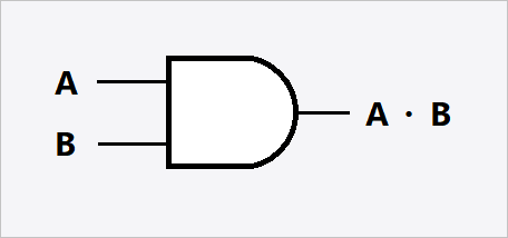
Here, you can see two different wires going into the AND gate, namely A and B. Each input can be in one of two states; either there’s electricity flowing through that wire or not; that is, it’s either a 1 or a 0. This is the origin of “computers understand 0s and 1s”.
The resulting wire represented by A·B can also only ever be two outputs (well… like all wires, there’s either electricity flowing through the wire or not; that is, 1 or 0). But for an AND gate, the result wire A·B is only ever 1 if BOTH A and B are 1 (that is, if and only if both A and B have electricity flowing through them, will the AND gate allow electricity out). That’s the “logic” part. How does the AND gate work? We’ll have to look into the transistors that make up the logic gate and to keep things simple, we’ll have to skip that part.
Anyways, the function of a gate can be represented in a tabular format popularly referred to as the Truth Table. Let’s take a look at what the truth table of an AND gate looks like.
| A | B | A·B |
| 0 | 0 | 0 |
| 0 | 1 | 0 |
| 1 | 0 | 0 |
| 1 | 1 | 1 |
As you can see in the above table, only when A and B are both 1, the result is 1. In every other scenario, the result is a 0.
The OR Gate
Just like the AND gate, there are several logic gates that are of interest to us. Firstly, there is the OR gate whose output results in a 1 if EITHER A or B are a 1. The truth table would look as follows
| A | B | A + B |
| 0 | 0 | 0 |
| 0 | 1 | 1 |
| 1 | 0 | 1 |
| 1 | 1 | 1 |
The XOR Gate
Then there’s the XOR (mutually exclusive OR) gate, whose result is a 1 if EITHER A or B have a 1 but not both. The truth table looks as follows.
| A | B | A ⊕ B |
| 0 | 0 | 0 |
| 0 | 1 | 1 |
| 1 | 0 | 1 |
| 1 | 1 | 0 |
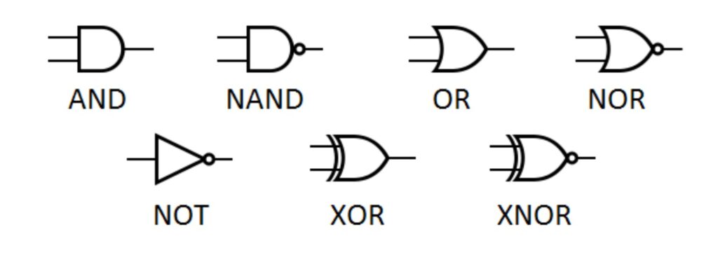
There are several other logic gates out there. Each is represented by a unique symbol assigned to it.
Alright! So now that we understand logic gates a little better, let’s go one step higher and make something meaningful out of these logic gates. Before we do that, I want to take a quick detour and explain binary numbers.
Binary numbers 101
In the decimal system, we use a base of 10. What that really means is, there are only 10 numbers (0 to 9). So, when you perform 9 + 1, you really have no other number left. So to solve this dilemma, what you end up doing is, you reset back to 0 and carry over the spillage to a new place resulting in 10. The 1 in the 10’s place basically indicates that the original number can be represented as 10 * 1 + 0. So taking a random number, 125, this is basically 10^2 * 1 + 10^1 * 2 + 10^0 * 5 (no surprises there I hope?).
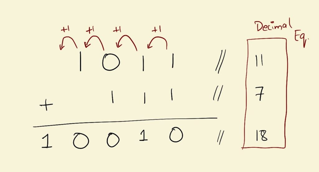
Binary numbers follow all the same rules except using a base of 2. So instead of the flip-over happening at 9, it happens at 1. A binary number 1011 is nothing but 2^3 * 1 + 2^2 * 0 + 2^1 * 1 + 2^0*1 which equals the number 11. The rules for addition for example are the same too.
Our little adder circuit
Alright, so now, we’re going to challenge ourselves a little bit. Let’s construct a circuit that adds 1-bit numbers (a bit is a fancy way of saying a binary number) using the logic gates we’ve learned about.
Some quick binary math first
I like to start off in these situations by constructing the truth table first and then building the circuit accordingly. Let’s see if we can piece this together. In all the truth tables so far, we’ve only had a single output. But for my adder, let’s have two separate outputs, Sum and Carry-Over.
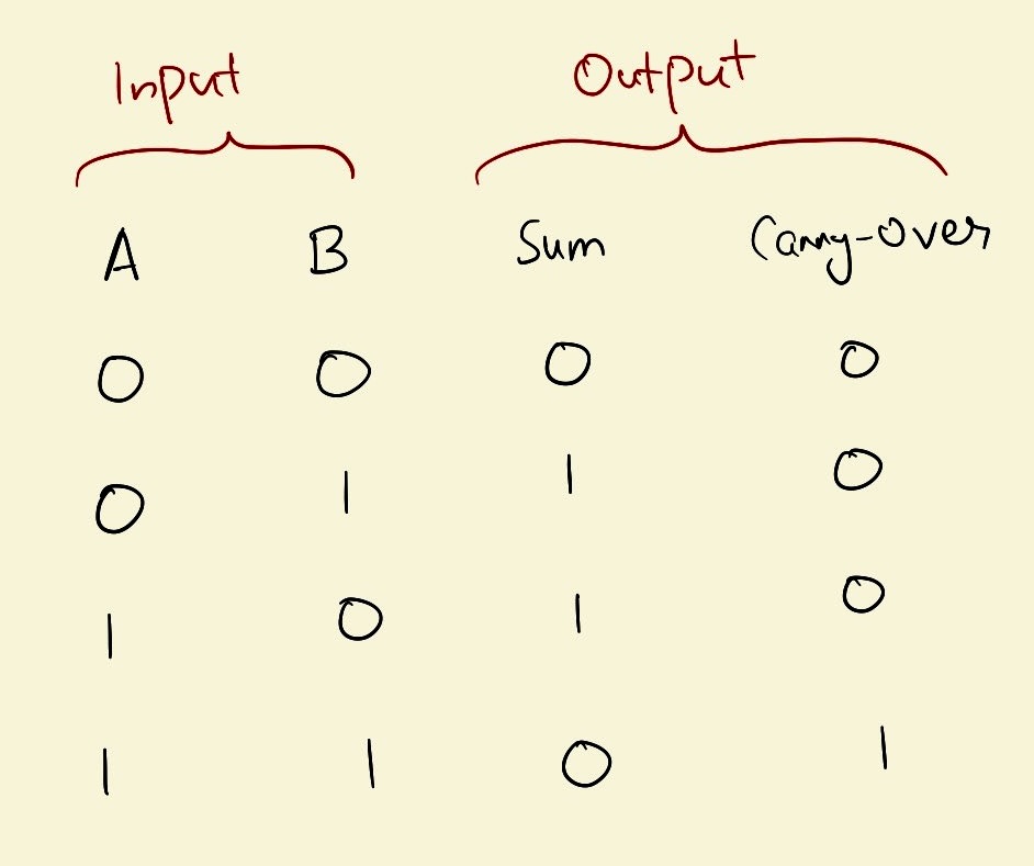
Carry-Over will represent the part that gets carried over during addition (if any). Sum will represent the part that we write down. Don’t worry if this didn’t make any sense. This part should help clarify it.
Okay…? How did I do this? Let’s walk through this table a little bit. So since I expect this bit to be a little confusing, I’ve broken down each case one by one.
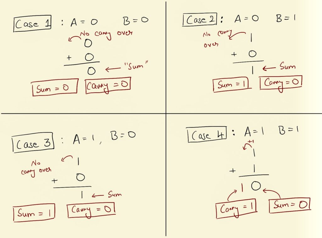
We’ve defined Sum to be what we write down (completely ignoring the carry-over). Carry-Over is the part that gets actually carried over. If you look at Case 4 specifically, the sum of 1 and 1 is 10 in binary. The Sum part of that would be the 0 we actually write down and output the carry over in its own output.
So now, I hope you’re convinced that the truth table for our addition checks out. Based on the truth table, let’s try to reverse engineer the circuit we would require to produce the same output as our truth table.
Time to build the circuit
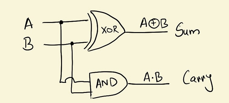
First, let’s figure out how we’d generate the Sum column given inputs A and B. If you refer back to the truth table of the XOR gate (don’t be lazy. scroll back up and check the truth table for the XOR gate), you’d see that the Sum column is nothing but the XOR of A and B.
Secondly, if you look at the Carry column in the truth table, you’ll see that the Carry column is nothing but the AND gate’s truth table with respect to inputs A and B.
So there we go! Let’s see what the circuit would look like for a 1-bit adder. The circuit would take two inputs, and spit out two outputs, which would be the Carry and the Sum.
Putting all of this together
From here, we can work our way further. The above circuit adds two 1-bit numbers. If you want to add two 2-bit numbers, you chain similar circuits together (you’d also use the Carry as an input) until you have an adder for a 2-bit number.
Remember our function add_numbers in the last post? We defined a function and invoked it later by calling its name along with the arguments as its input. A modern processor does something similar. The processor in your computer comes with an “instruction set” which is a set of basic instructions that the processor is able to perform. (Here is an example set of instructions that the x86 family of microprocessors use). When you write any piece of code, you run it by another software to convert it from the human-readable version into a series of instructions that your computer can actually understand (instructions that are specified in the instruction set).
For example, the x86 instruction set supports the ADD instruction which adds two 64-bit numbers. (Just take the 1-bit adder circuit, chain it up a few times and make a 64-bit adder). When your compiled code contains an ADD instruction, your computer takes the two binary numbers and passes electricity through just the wires that are specified by the input numbers. The circuit logic will “do the addition” by essentially looking at which output wires contain electricity.
And that’s a wrap!
We started from a basic logic gate, something that took two 1-bit binary numbers and implemented some bare minimal logic. Out of that, we built an adder which combined some of these logic gates to do something more. We then chained several of these 1-bit adders to get a 64-bit adder. And now, each time your computer runs any program, electricity flows through this circuit to do your computation.