
The advantage of a bad memory is that one enjoys several times the same good things for the first time.
― Friedrich Nietzsche
As a laptop or smartphone owner, you’re probably familiar with the amount of memory your device has. You are also likely aware that there are two types of memory that your device uses. For instance, let’s consider the latest MacBook Pro 13.
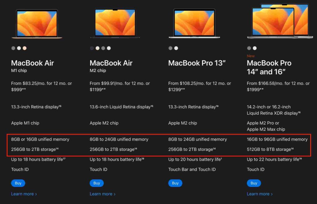
The first line describes the RAM of each device, followed by the second line, which specifies the amount of secondary storage. Although both types of storage have distinct functions, they are equally essential for optimal device performance.
What are they
The primary function of secondary storage is to provide a permanent storage solution for your files, preventing data loss upon system restarts. Compared to RAM, which is designed to be fast and serve as the working memory for the CPU, this type of storage is cost-effective. For example, the M1 chip with its 16 cores can execute 11 trillion operations per second, requiring the RAM to be equally fast to avoid slowing down the CPU. RAM is costly and stores temporary data that is frequently cleared. In addition, RAM must be random-access, ensuring uniform memory access time.
The CPU can only access data stored in RAM, which means that anything a computer runs must be loaded into RAM first. Suppose you create a program that reads a text file with 10 numbers, adds them up, and writes the result to another file. In that case, your CPU will first direct secondary storage to copy the numbers to the RAM. The CPU will then execute the code to sum each number, updating the result in the RAM, and instruct secondary storage to write the outcome to a file.
A closer examination of RAM’s hardware implementation is required to gain a better understanding of how it works.
The RAM in your computer
Although there are various ways to implement a circuit that can achieve the same end result, for the purposes of this discussion, I will be using a basic DRAM (which is one way to implement RAM).
A quick detour
Before we go any further, we need to look at two components; the transistor and the capacitor.
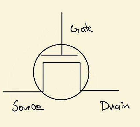
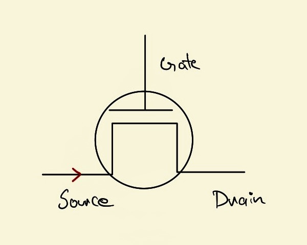
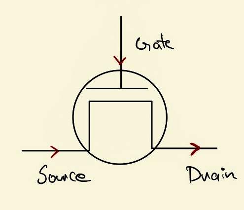
The transistor is an electronic device that can be used as a switch or an amplifier. It has three terminals called Source, Gate, and Drain. When a current is applied to the Source terminal, it will only flow to the Drain terminal if a current is also applied to the Gate terminal. The Gate terminal acts as a control switch, determining when the current from the Source flows into the Drain. This property of the transistor allows it to be used in a wide range of electronic applications, from digital logic circuits to power amplifiers.
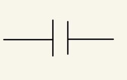
The second piece of circuitry would be the capacitor. A capacitor is a device capable of storing some amount of electric charge. You can think of it as a tiny water tower of electric charges. You can “recharge it” by passing a current through it and “discharge” that charge later. This is how a capacitor is represented.
Memory Cell
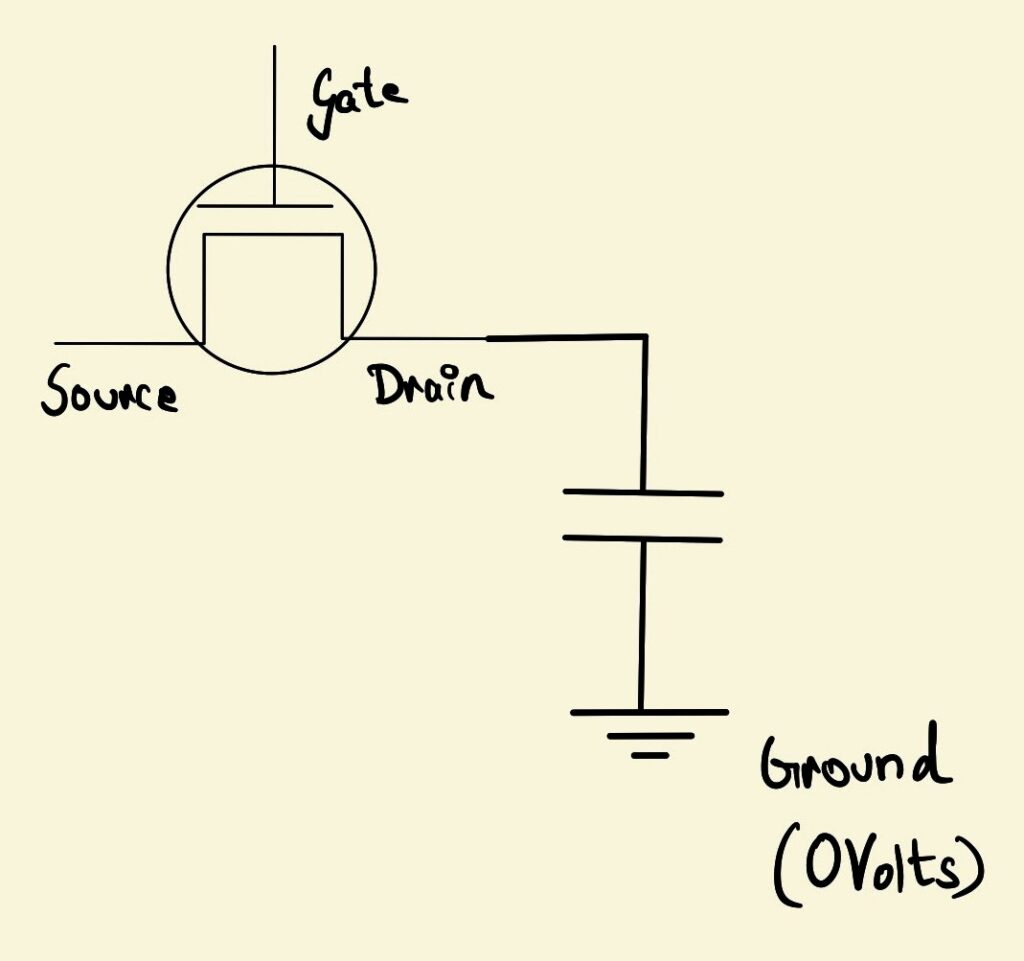
Now, we can put the two of these circuits together to build a circuit that stores one bit of information. We’ll call this a memory cell.
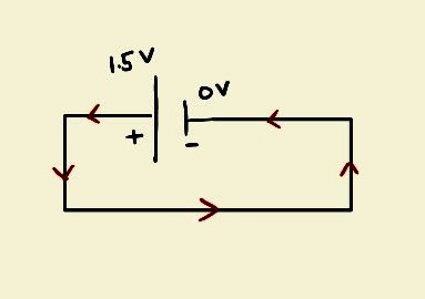
A quick recap on some physics here: To understand how electricity flows in a circuit, it’s important to remember that current only flows when there is a difference in voltage between two points. This difference in voltage is often referred to as a voltage “potential.” Conventionally, current flows from the positive end of a circuit to the negative end. For example, in a 1.5V battery, the positive end is at a voltage of +1.5V, while the negative end is at a voltage of 0V which results in a current flowing from the positive end of the battery to the negative.
Returning to the memory cell circuit, we now need to perform hardware operations on it. We will define the state where the capacitor has stored charges as “1”, and the state where the capacitor is drained or has no stored charges as “0”. These states will be used to represent the data stored in the memory cell. Let’s call these functions SET() and UNSET().
SET()
Suppose we have a hypothetical function that sets the memory cell to “1” by charging the capacitor. To do this, we need to apply a current by setting a higher voltage at both the Gate and the Source of the transistor. To do this, we set a voltage across both the Gate and the Source. The current, therefore, passes through to the drain and flows into the capacitor thereby charging the capacitor.
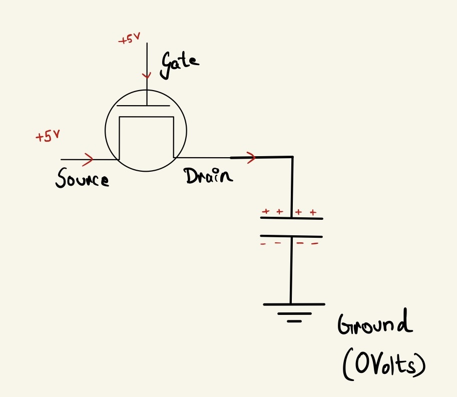
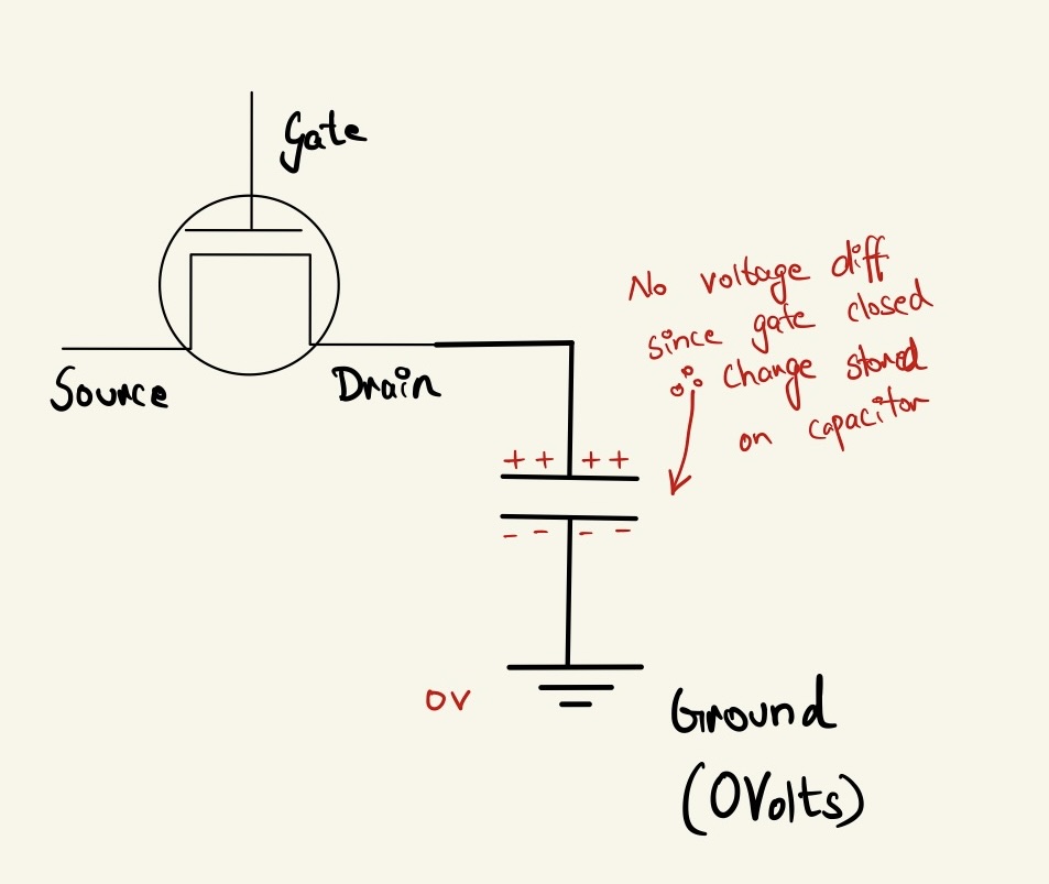
Cut off voltage at the Gate to cut off the current flow. This will result in the capacitor having stored some charge but being unable to discharge it back out since the gate is closed.
UNSET()
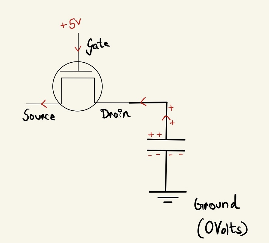
To unset the memory cell or drain the capacitor of its stored charges, we simply need to open the Gate of the transistor by setting a high voltage at the Gate and grounding the Source (setting it to 0V). This breaks the connection between the Source and the Drain, providing a path for the stored charges in the capacitor to flow out through the Source wire, effectively draining the capacitor. By doing so, we set the memory cell to “0”, which represents the absence of stored data in the cell.
Okay! So we are now covered in setting and unsetting the memory cell. We can extend the UNSET operation to perform a READ operation.
READ()
So during the UNSET operation, you allow the charges to flow back out through the Source wire by enabling the Gate and grounding the Source. Now say we had dedicated hardware plugged into the Source wire that was capable of detecting changes in voltage on this wire. So when the charges of the capacitor flow into the Source wire, there is a tiny difference in voltage across the Source wire which can be detected.
This is pretty much how a read operation takes place. The capacitor is allowed to temporarily discharge just a little bit so that the voltage difference can be sensed.
This does mean that you need a separate circuit to refill the charges lost during reads and this process is referred to as Memory Refresh you can read more about it here.
Now, it’s time to build ourselves some RAM!
Let’s construct our RAM
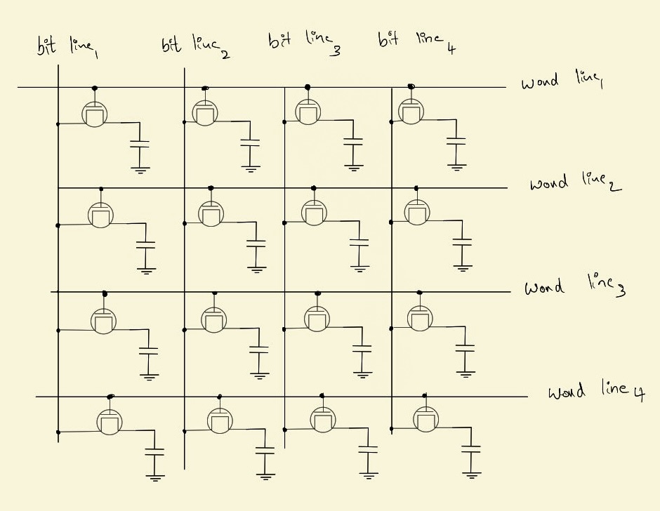
To construct our RAM, all we have to do is to arrange a whole lot of memory cells in a grid.
In practice, it’s not very useful to be able to read just one bit at a time. Modern computers define their own unit of memory known as a “word.” A word is a fixed-size block of memory that the computer can manipulate as a single unit. For instance, the M1 chip uses a 64-bit word size, which means that it deals with memory in blocks of 64 bits rather than individual bits.
By organizing memory into words, computers can read and write data much more efficiently. For example, when a computer reads a 64-bit word from memory, it can process 64 bits of data at once, which is much faster than reading each individual bit separately. This approach also helps to simplify the memory addressing and management process, making it easier for the computer to access and manipulate large amounts of data.
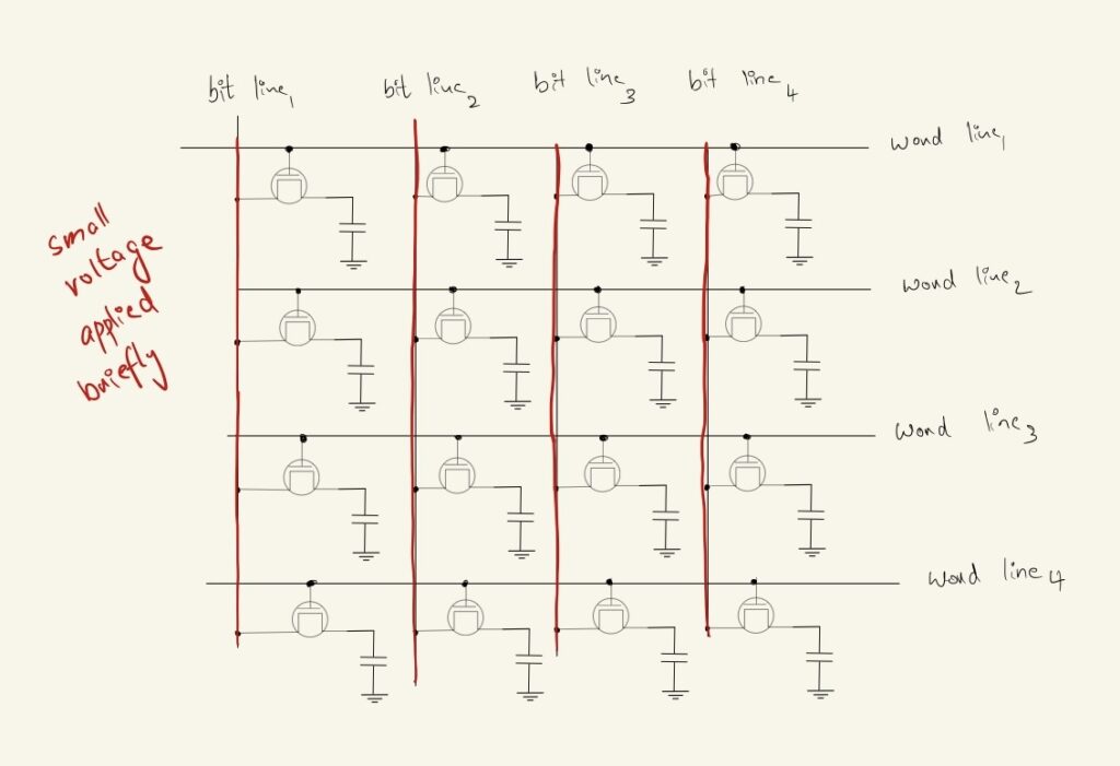
To understand how memory is organized in modern computer systems, we can take a look at the concept of word lines and bit lines. Word lines are a set of electrical wires that connect to each row of memory cells, while bit lines are another set of wires that connect to each column of memory cells. The number of word lines is determined by the amount of storage available in the chip, while the number of bit lines is typically the same as the word size.
For example, the 8086 processor uses 16-bit words, which means that each word has 16 bits. This means that there are 16-bit lines, one for each bit in the word, and the number of word lines depends on the total amount of memory available in the system.
Reading From RAM
So say you want to read the 3rd word in memory.
We kick things off by slightly charging up all the bit lines in our circuit with a small voltage. This keeps the current ready to flow at the Source but is unable to do so since the Gate is closed.
Now, set a voltage across the 3rd-word line
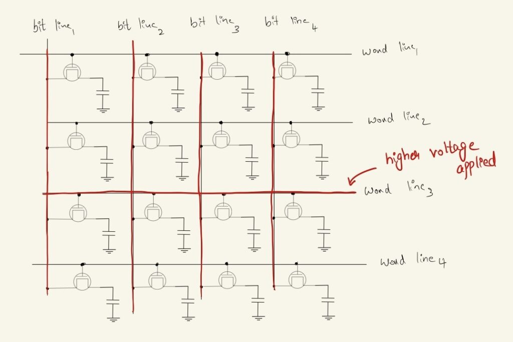
We’ve effectively opened the gate for all the transistors for word line 3. One of two things can happen at each bit line
- The capacitor it was connected to was charged. The capacitor’s potential is stronger than the mildly charged Source wire, therefore current flows from the capacitor into the bit line. (this is why we intentionally applied a lesser voltage on the bit lines). This flow of current into the source wire/bit line leads to a slight increase in the voltage at the bit line which can be detected as a
1. - The capacitor it was connected to was empty. Now, the current from the bit line is able to flow into the capacitor. This loss of charges on the bit line leads to a slight reduction in voltage across the bit line which again can be detected as a
0.
After the read, to make up for the lost charges, the hardware that detected the voltage difference also re-writes into the capacitor that lost charges and drains the capacitor that had some charges flowing into it.
And there you have it, we’ve effectively built a miniature version of a RAM using a 1T1C (1 Transistor / 1 Capacitor) memory cell!
A Wrap for Part 1
The original plan was to write about how secondary storage works in the same blog post. But seems like we’ve covered quite a lot of new stuff already and anything new might just turn into an information overload. So let’s call it a day and continue the remaining of this blog in another post. If you’re looking for more interesting reads, check out how a computer actually manages to do math here.