

In the last post, we covered ELFs and memory layouts. I concluded the article with the promise of walking through an example program in execution to help visualize things better.

I’m sorry but this new stuff seemed more appealing 😔. We could probably follow it up in a separate post but for now, let’s jump straight to the Raspberry Pi!
Plugging it in
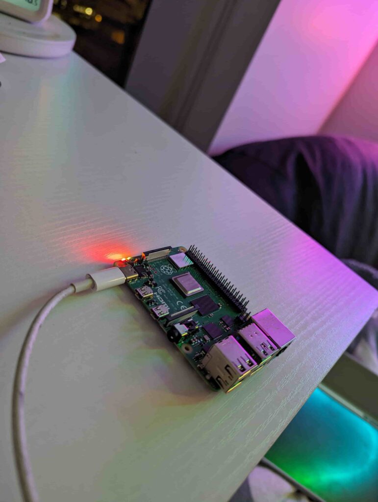
Nothing happened. Why? For starters, we have no output devices for the Raspberry Pi to convey any information to us. And more importantly, we don’t have any software on this Raspberry Pi that could put our output devices to use.
Computers come with very little pre-packaged code; stuff like performing basic checks to ensure the hardware is functional. But apart from that, it has just enough code to load your operating system. The operating system then takes care of everything else.
For Raspberry Pi, I think the sequence of operations looks something like this
- Perform hardware checks
- Load the operating system from the SD card with a file named
kernel8.img.
Let’s start with the operating system for our Raspberry Pi; Raspbian; an operating system built by the company manufacturing Raspberry Pis. I’ve downloaded this onto an SD card. This is what the contents look like.

My guess is as good as yours on what these files are. But I do recognize the kernel8.img file on the SD card. That is the ELF executable of the operating system that is run when the Raspberry Pi is booted. In other words, it’s the “.exe file” of our operating system. (It uses an ELF file type because Raspbian is built on top of Linux).
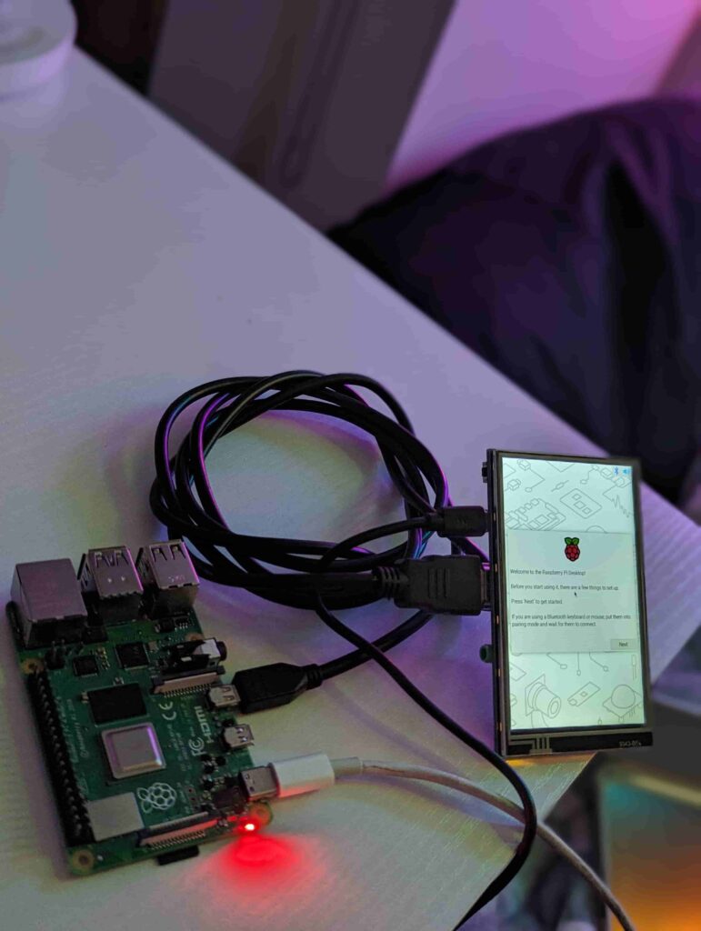
If I boot the Raspberry Pi with the SD card plugged in, the logo pops up on the display alongside a welcome message.
Your operating system converted the hardware you had into a fully functioning computer ready to be used. So how does the operating system do this? What does the code interacting with hardware look like?
Write your own OS
I need to start this section with a disclaimer. I have next to no practical experience working with hardware. A whole lot of this is new to me; best practices are not expected to be followed and mistakes are expected to be made ^_^.
With that, let’s get started. In our previous post, we’ve seen what ELF files are, and how they are combined to form an executable file. We’ll also start using C rather than writing this in assembly. I mean… I’m bored, but I’m not that bored.
Let’s start with a bare minimal operating system that does nothing.
void main() {
    while(1);  // Loop infinitely; do nothing
}
(Note: Programs start execution at the main function by default). Let’s build this into an ELF file, load it into our SD card, and see what happens.
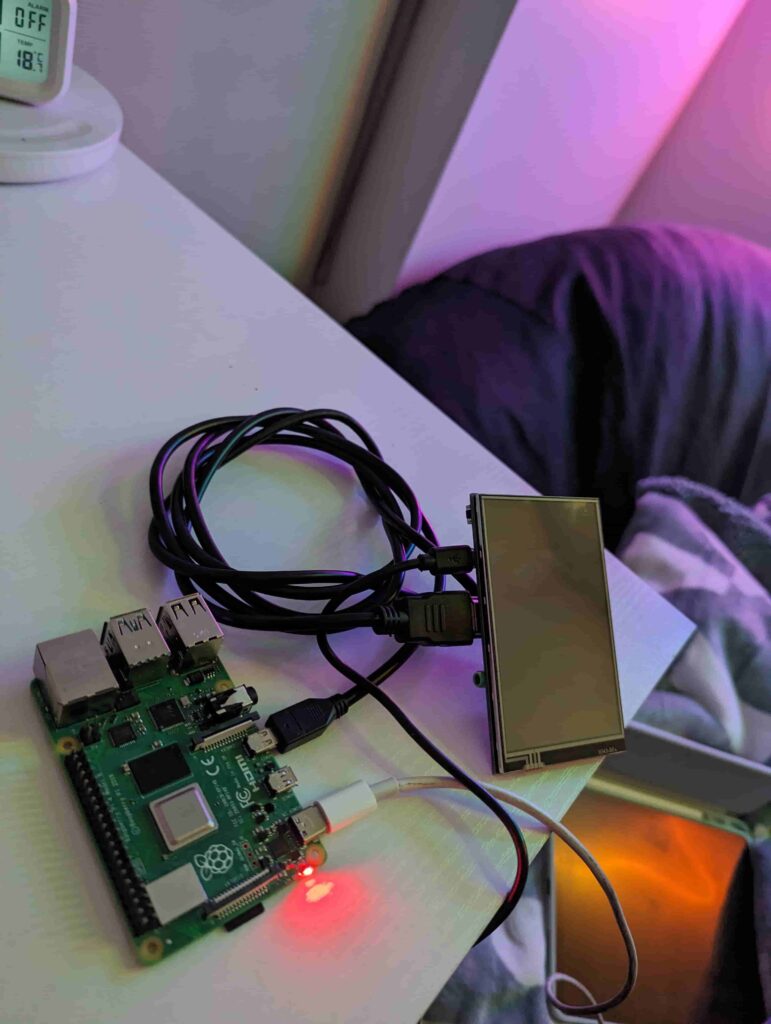
Aaaand lights out. Obviously, our operating system right now does nothing. It might not look like much but right now, our CPU is working pretty hard on that infinite loop. However, some proof of life would be nice. We could start writing code that prints “Hello World!” onto the screen. That would be a great way to verify that our operating system is working as expected. However, writing to a display isn’t as straightforward as we’d imagine. We’ll get to it in a future post but for now, let’s start small.
Making an LED Blink
Taking a look at the Raspberry Pi model again, we see the 40-Pin General-Purpose Input/Output GPIO. We’re going to control these pins to make our Raspberry Pi do something useful.
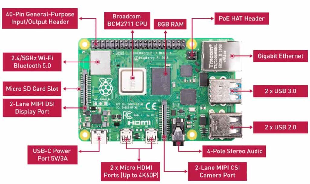
Let’s take a closer look at the layout for these pins (found this in the documentation).
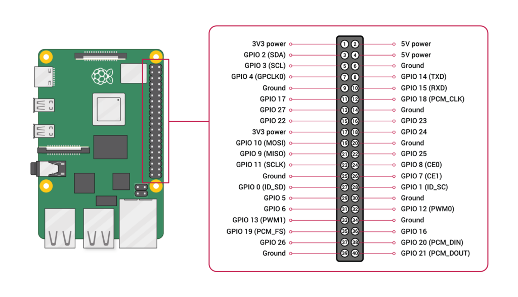
Each of these pins has a base function. For example, Pin 1 is marked as 3V3 power. This means that Pin 1 is at a +3.3 Voltage. Similarly, Pin 6 is marked Ground or 0V. So if I connect an LED bulb marked for 3.3V across Pin 1 and 6, I should expect it to glow.
Some pins are also labelled with a GPIO number, like Pin 3 marked as GPIO 2. These pins are of interest. The pins marked GPIO can be programmatically controlled. For example, your code could set the pin to output 3.3V (HIGH) or ground the pin to 0V (LOW). So if I connected the same LED across Pin 3 (GPIO 2) and Pin 6 (Ground) and alternated Pin 3 between 3.3V and 0V with a pause between each switch, I’d make the LED blink!
Then, the last piece of the puzzle would be, how do we control Pin 3 (GPIO 2) with code. For this, we’ll need a quick detour to explain Memory Mapped IO.
Memory Mapped IO
As covered in an earlier post, your RAM has memory addresses which refer to the memory locations in your RAM. They’re almost like coordinates on your RAM. Your CPU reads/writes to your RAM via memory addresses; “store the number 50 at address 0x80000000 (hexadecimal)” or “read the value present at address 0x125AF724”. However, your CPU also reserves some addresses that don’t really correspond to any location in the RAM. Instead, these addresses map to your IO devices. When you read/write to these addresses, your CPU knows you’re trying to access hardware and takes care of interacting with the hardware. For example, your CPU documentation could specify that, on writing the number 1 to address 0x70000000, it sets the GPIO 2 pin to 3.3V.
This model of virtualizing the hardware with memory addresses is referred to as memory-mapped IO. It makes it awfully convenient to write code. You write to these memory addresses as you would for reading/writing data to RAM and your CPU takes care of the rest.
Manipulating the pin
At this point, we’re ready to manipulate the pin to make our LED blink. Let’s refer to the documentation on the memory address of the GPIO Pins. Taking a look at the BCM2711 peripherals documentation (the CPU used on our Raspberry PI), we see several registers along with their memory address and function, we’ll need several registers but let’s just focus on one for now.

The documentation further explains what GPSET0 does here.

tldr; to set the GPIO Pin n to a high (3.3V) voltage, we have to set the nth bit of this memory address to a 1. So in our case, setting this memory address to binary 00000000 00000000 00000000 00000100 (2 in decimal) would set GPIO Pin 2 to High. There’s a similar memory address GPCLR0 for which setting the same value would clear GPIO Pin 2. Let’s see what the code looks like.
enum {
    BASE = 0xfe200000,  // Base address of the registers according to the docs
    GPFSEL0 = BASE + 0x00,  // Offset from the base (refer to register view image)
    GPSET0 = BASE + 0x1c,
    GPCLR0 = BASE + 0x28,
};

volatile unsigned int *register_gpfsel0 = (volatile unsigned int*) GPFSEL0;
volatile unsigned int *register_gpset0  = (volatile unsigned int*) GPSET0;
volatile unsigned int *register_gpclr0  = (volatile unsigned int*) GPCLR0;

void clear_pin(int pin_number) {
    *register_gpclr0 |= 1 << pin_number;
}

void set_pin_as_output(int pin_number) {
    *register_gpfsel0 |= 1 << (3 * pin_number);
}

void set_high(int pin_number) {
    *register_gpset0 |=  1 << pin_number;
}

void spin_wait(unsigned long n) {
    for (unsigned long i = 0; i < n; i++);
}

void sleep() {
    spin_wait(1000000);
}


void blink_led() {
    set_high(2);
    sleep();
    clear_pin(2);
    sleep();
}


void main()
{
    set_pin_as_output(2);
    while (1) {
        blink_led();
    }
}
Code Walkthrough
There’s quite a lot going on here. Let’s break it up into pieces to better understand.
enum {
    BASE = 0xfe200000,  // Base address of the registers according to the docs
    GPFSEL0 = BASE + 0x00,  // Offset from the base (refer to register view image)
    GPSET0 = BASE + 0x1c,
    GPCLR0 = BASE + 0x28,
};

volatile unsigned int *register_gpfsel0 = (volatile unsigned int*) GPFSEL0;
volatile unsigned int *register_gpset0  = (volatile unsigned int*) GPSET0;
volatile unsigned int *register_gpclr0  = (volatile unsigned int*) GPCLR0;
We start by creating three variables register_gpfsel0, register_gpset0 and register_gpclr0 that point to the memory addresses specified by GPCLR0, GPSET0 and GPCLR0 respectively. These are the addresses that we found in the documentation. Essentially, we’ve created handy variables to read/write to these memory-mapped addresses.
void set_high(int pin_number) {
    *register_gpset0 |=  1 << pin_number;
}
We then created several functions that abstract away the registers and make it more intuitive to use these addresses. The set_high , for example, sets the right bit for a given pin_number to a 1. We do this based on the documentation specified for the GPSET0 register. For example, calling the functionset_high(2) sets the bit associated with GPIO 2 to a 1, consequently setting GPIO 2 to a high voltage.
void blink_led() {
    set_high(2);
    sleep();
    clear_pin(2);
    sleep();
}


void main()
{
    set_pin_as_output(2);
    while (1) {
        blink_led();  // call blink_led function in an infite loop
    }
}
Putting it all together, our new main function initializes GPIO 2 and goes into an infinite loop that calls the blink_led function. What does this function do? It first sets GPIO 2 to a HIGH, proceeds to sleep for a fixed duration, clears GPIO 2 and goes straight back to sleep.
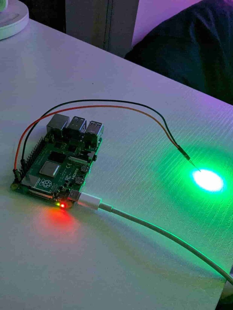
Repeat this an infinite amount of times and you should get a blinking LED light. Let’s build this and plug our new operating system into the Raspberry Pi.
Success! Proof of life for our “operating system”!
Wrapping it up
At this point, we’ve successfully manipulated some hardware with code even if it’s just to blink an LED bulb. However, that’s pretty much all our operating system supports. It’d be cool if our operating system could do a little more than what it is currently capable of. But for now, we’ve covered enough to call it a day.